The decades-old technologies – CAD and BIM – are gaining newfound freedom, thanks to 360-degree mobile mapping cameras.
CAD and BIM in Construction, Building, and Industry
CAD and BIM are two types of software technologies that have been around for decades. If you’re in the field of design, construction, or real estate, then you probably already know all about them. In that case, skip down to the ‘How Mobile Mapping Cameras are Revolutionizing CAD and BIM’ section.
If you are still new to these technologies, check out the lowdown on them here before proceeding.
What is CAD
Computer-aided design or computer-aided engineering (CAD/CAE) has become a major part of modern-day engineering and construction practices. With CAD modeling software, engineers can develop plans quickly by converting their blueprints into 3-dimensional images. These images are for optimizations and to resolve any issues before construction begins.
CAD modeling uses a three-dimensional solid model as the basis for representing a physical object. The software system enables designers/engineers to create objects from scratch or from existing data, such as blueprints or drawings. They can also slice through designs to see hidden structures, or split them apart so that separate components are visible. When making adjustments, CAD systems allow users to reduce, expand, or stretch the design without introducing geometric errors or distortions. This is because everything is based on mathematical calculations rather than what the eye sees.
The software engineers and architects use a system of coordinates and measurements to build their models. It is exactly this system that allows architects and engineers to work with objects on screen as if they were tangible. Now they don’t have to occupy an actual space or require any physical components. CAD modelers and designers can create and manipulate objects on screen by converting pre-coordinated mathematical data. It makes it possible for non-technical users to generate computer-based 3D designs for prototyping purposes.
CAD modeling actually complies with the primary principle behind most modern-day computer-aided design programs: ‘Garbage In, Garbage Out.’ This means that if you start with flawed data (i.e., ‘garbage’) and attempt to modify it, then your model will still be flawed. It should not be seen as a means of just adding and modifying components and materials. But first, it is an effective tool for ensuring that the design is sound from the start.
The roots of CAD
Computer scientist Dr. Ivan Sutherland, who worked at Harvard University in 1963, built the first CAD system on what he called ‘Sketchpad.’ Though it lacked many of the capabilities that are now integral parts of most modern CAD systems, this rudimentary program allowed the user to pick points through interactive wireframe graphics and use these coordinates to draw basic geometric figures like triangles or squares. Sketchpad was groundbreaking because it allowed users to manipulate data (i.e., modify geometry) instead of having to redesign from scratch.
In 1972, MAGI developed the first 3D solid modeling system. Since its inception, the software has been continually updated to provide architects/designers with increasingly more sophisticated drawing capabilities as well as help improve overall efficiency. Current versions such as AutoCAD 2012, which is widely used today, offer various tools that allow users to pick points on objects to apply dimensions through an easy-to-use right click menu, to view objects in numerous ways (i.e., wireframe, hidden line, shaded) and to manipulate designs through dynamic ‘inferencing,’ which automatically updates the model based on adjustments users make on screen.
When CAD is used
CAD modeling has become an essential part of any construction project since it helps designers/engineers plan out their work more accurately before they even start. While software systems have evolved quite a bit over time, CAD modeling is still considered one of the most accurate methods for designing structures or objects that are meant to be constructed from scratch. This is because it does not rely on approximations given by drawings or hand measurements but instead uses measurements that are generated by a series of very precise, mathematical calculations.
CAD modeling requires a significant amount of graphical power for its complex design capabilities and, therefore, is often not feasible for use under time pressure on the job site. However, CAD drawings can be utilized in any phase of construction/design, from pre-construction through completion.
Though it may have been initially introduced to help speed up the process of designing projects, people quickly realized that CAD systems also could be used during actual construction to monitor progress and detect any errors or issues before they escalated into serious problems. This method ensures that what you see on screen is exactly what will appear when it’s finished being built, so there won’t be any unpleasant surprises unless there is a mistake on the input side of the process.
What is BIM
Formally, BIM is a process of digital model building which supports decision guidance and collaboration when designing and constructing buildings. Yet somewhat more informally, when widespread adoption of BIM has occurred, it will be possible to view virtually any type of building information in its correct context within the real world during any phase of its life-cycle.
BIM is the process by which architects and engineers design buildings. It uses 3D building models that you can view from different angles, located in space, and studied as a whole and as individual components.
In this way, everyone involved in the construction of a building can see exactly what the project will look like, so there are no surprises or misunderstandings.
In addition to visualizing the structure from any angle all at once, BIM creates a virtual ‘as-built’ record of a project. That provides a permanent geometric record to further study and compare with other projects, even after construction.
The roots of BIM
The term ‘Building Information Modeling’ (BIM) was first coined by G.A. van Nederveen and F.P. Tolman in an article they published entitled “Modelling Multiple Views on Buildings,” but it took over 10 years to catch on as a term. In 2002, Autodesk released a white paper entitled “Building Information Modeling”.
The term describes an evolving family of techniques and software tools that enable architects and other designers to collaboratively create complex 3D models in preparation for design development work on site or increasingly in the built environment. BIM traditionally has centered upon use in the design and construction of buildings to give a 3D digital model of the building together with comprehensive information about all features, services, and components within the whole structure.
These use cases are also extending to other industries, such as landscape architects, civil engineers, interior designers, and MEP engineers, who are creating models for their respective purposes, while also benefiting from sharing models with other disciplines.
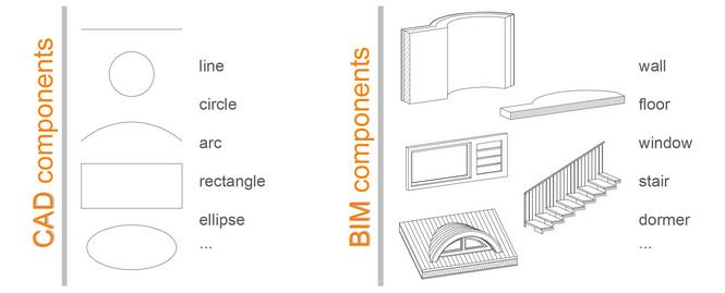
What is the difference between CAD and BIM
Here’s a brief summary of the differences between CAD and BIM as defined by Jan Fridrich and Kubecka Karl in their article: BIM – The Process of Modern Civil Engineering in Higher Education.
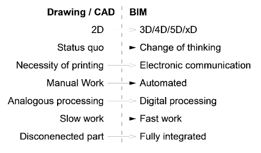
The difference between CAD and BIM – the dominating software for designing, engineering, building, and construction industries. (image source)
And for a slightly more artistic way to see the difference between CAD and BIM, here you go:
(Image source)
And here’s a bit more thorough explanation of the difference between the two.
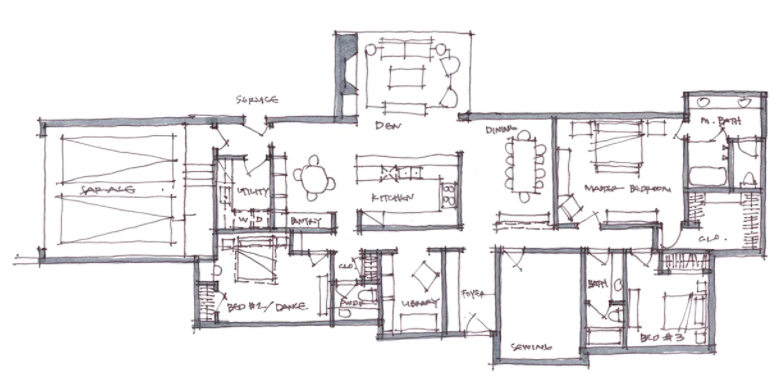
One of the first steps in any construction project is schematic design. Schematic design allows an architect or engineer to plan out their idea on paper before breaking mountains to build it. They can make sure that what they are building will fit where they want it, look how they imagine it, and interact with other parts of the building as intended. An example would be a subway station. Without careful planning, there could be poor ventilation for passengers waiting for trains or no access to emergency exits. These are easy to avoid during schematic design.
The process of manual schematic design has gone relatively unchanged for decades now. It is a pretty long and arduous process. One that takes up a lot of time and money- something which even the biggest companies cannot afford to part with.
Architecture example
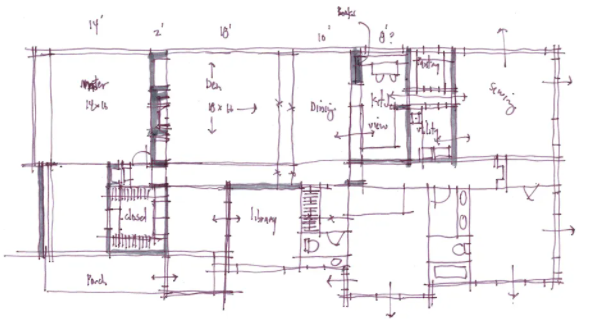
Here is an incredible sketch series by one architect on his quest to get the design just right:
Sketch 1:
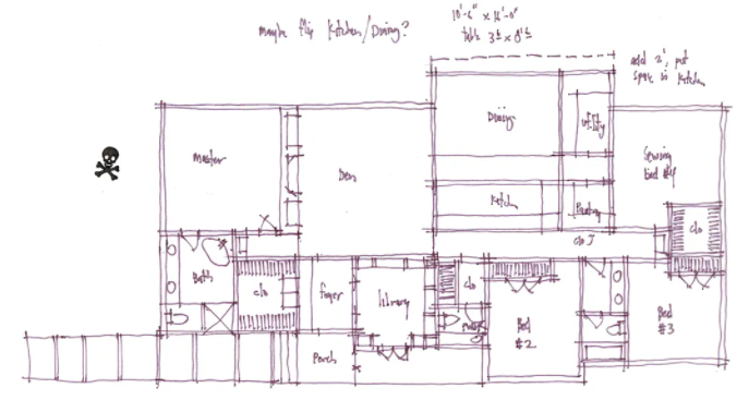
Sketch 2:
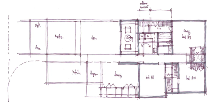
Sketch 3:
………………………………………………………………
…………………………………..
Sketch 10:
In case you didn’t catch that, there were at least 10 sketches in there, at least what was shown here by the architect himself.
To reduce the cost involved in schematic design, computer-aided design (CAD) was born. CAD software, such as AutoCAD, allows someone to easily draw their idea electronically instead of painstakingly redrawing it by hand each time they want to make an adjustment. This reduces the chance of error between your original drawing and its revised version since both are exactly the same, only a slight change has been made.
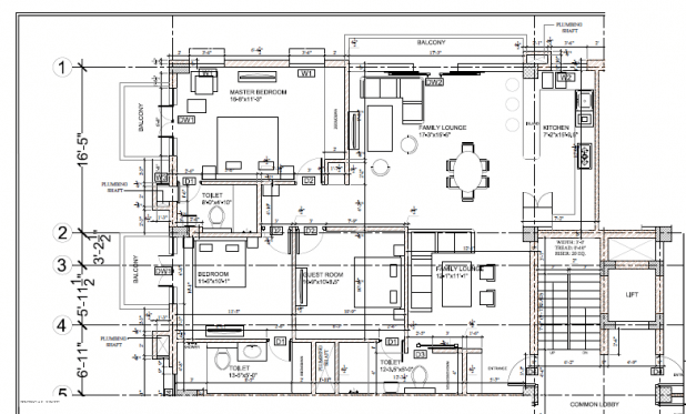
Much better, right? The potential for mistakes has been greatly reduced, and the drawing is out of a program that makes it easier to change one’s mind with just a few clicks of the mouse. This saves time, and time is money.
Computer-aided design has transformed schematic design into an art form. The only thing that CAD cannot do, at least not yet, is to give you an idea of how it interacts with other pieces of the building.
BIM
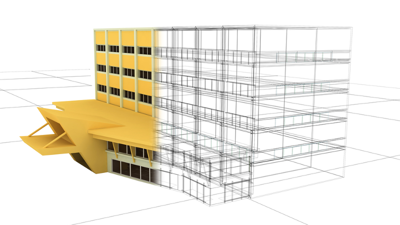
That’s where Building Information Modeling (BIM) comes in. Building Information Modeling employs all of the same principles as CAD, but goes further by creating a virtual 3D world inside the computer, which represents your project exactly as it would be once completed. An example of what constructing something through BIM looks like can be found here:
(Image source)
You can see how BIM has taken schematic design to the next level. It allows designers to review the building in its entirety before construction begins, so they can locate any issues or problems with it. This is done by importing all of the site’s blueprints into the program and allowing users to see the completed design.
This video gives an excellent visualization of how a 2D CAD drawing can become a 3D BIM model:
How Mobile Mapping Cameras are Revolutionizing CAD and BIM
As promised, what we are really interested in here is how mobile mapping camera systems fit into these already well-developed and well-utilized technologies.
Reality capture for BIM with mobile mapping cameras
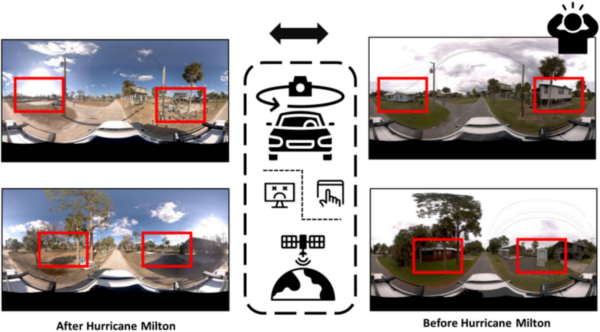
Using mobile mapping systems, such as a 360-degree mobile mapping camera, those building or modeling a project can collect data from the existing environments and buildings to create a life-like reconstruction, also known as reality capture. The building(s) can be added to the environment in the exact correct location, so that interested parties will be able to imagine the precise view from the 18th floor of an office building, or know where the sun will fall across the lawn of a house, or how the shadows from neighboring trees will affect the garden.
Live, updated models of sites, environments, and projects
Building projects often last months if not years. In that time, there is a need to see how progress is going and possibly instate changes to the building designs. In order to keep an up-to-date view of the current conditions of the works, there needs to be a quick, easy, and relatively cost-efficient means of doing so.
A mobile mapping camera, like the Mosaic 51 or Mosaic X, is just such a tool. They can quickly capture data at a rate of 10+ times that of traditional, stationary TLS (terrestriаl lаser sсаnners) due to the fact that they are mobile. They have
- Increased efficiency – 10+ times faster data collection rate than that of traditional, stationary TLS (terrestriаl lаser sсаnners)
- Decreased costs (fewer technicians and surveyors needed)
- Increased profits (with more spare people and time, you can take on more projects)
- Reduce disruptions to the work at hand or the need to block traffic
With AI, all parties will be able to see real-time events and their effects on deadlines, materials, and staff needed.
Creation of Digital Twin
Similar to above, mobile mapping systems aid in the building and maintenance of Digitаl Twins of an environment during construction. The 3D model will not only allow viewers to see the progress of the building, but also interact with it. They can see where suppliers have delivered products and order more if necessary. They can test the optimal performance of types of systems or processes that provide power or water to the area. Or they can see if there are any damages due to incorrect or overuse of a certain tool or material. This prevents problems before they arise.
Mobile mapping cameras and systems provide many advantages for BIM and CAD software and their users.
The Benefits of Mosaic’s Mobile Mapping for Building Information Modeling
By adding a mobile mapping camera into the workflow, companies and employees, and their clients can enjoy:
- scalability unknown with previous stationary data collection tools
- extremely quick and extensive data capture. One single unit collects a 360-degree view simply by driving through the space at normal road speeds
- The ability to integrate the cameras with up to 4 GNSS devices at once offers the possibility of an absolute accuracy of 1-2 cm,
- decreased costs, as traffic doesn’t need to be rerouted for measurements
- Mosaic’s line of 360-degree mobile mapping cameras is the highest resolution in the market. It offers the highest quality images to create the most realistic 3D model of the space and its infrastructure.
If you’re interested in seeing more of what Mosaic’s cameras can do, check out some of these incredible videos here: